About CCUS
Playing an important and diverse role in meeting global energy and climate goals
About this report
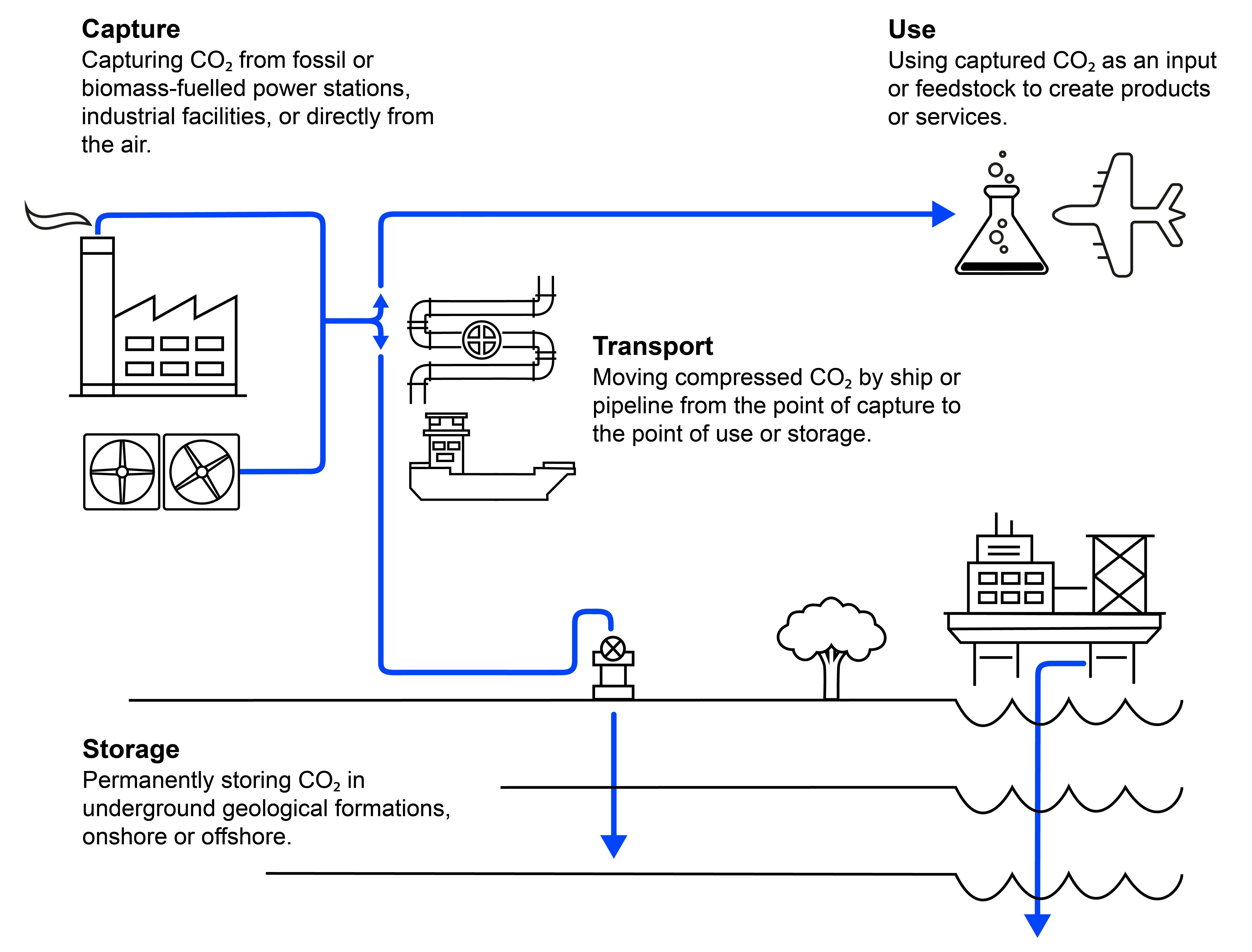
What is CCUS?

Where is CCUS happening?
Today, CCUS facilities around the world have the capacity to capture more than 40 MtCO2 each year. Some of these facilities have been operating since the 1970s and 1980s, when natural gas processing plants in the Val Verde area of Texas began supplying CO2 to local oil producers for enhanced oil recovery operations.
CCUS facilities in operation by application, 1980-2021
OpenSince these early projects, CCUS deployment has expanded to more regions and more applications. The first large-scale CO2 capture and injection project with dedicated CO2 storage and monitoring was commissioned at the Sleipner offshore gas facility in Norway in 1996. The project has now stored more than 20 MtCO2 in a deep saline formation located around 1 km under the North Sea.
Current CCUS projects around the world
Click a project for more information
Sources: IEA research and GCCSI (2021), Facilities Database, https://co2re.co/FacilityData
Stronger investment incentives and climate targets are building new momentum behind CCUS. The pipeline of planned projects is growing. Many of these plans involve the development of industrial “hubs” which capture CO2 from a range of facilities with shared CO2 transport and storage infrastructure. Examples include the Alberta Carbon Trunk Line in Canada, which started operating in 2020, and the planned Longship project in Norway.
CCUS around the world
In addition to the commercial CCUS facilities operating around the world today, there are a large number of CCUS pilot or demonstration projects as well as projects in earlier stages of development. Here we feature some globally-significant CCUS projects to highlight the breadth of activity across applications, sectors and regions.
How is CO2 captured?
CO2 capture is an integral part of several industrial processes and, accordingly, technologies to separate or capture CO2 from flue gas streams have been commercially available for many decades. The most advanced and widely adopted capture technologies are chemical absorption and physical separation; other technologies include membranes and looping cycles such as chemical looping or calcium looping. The various technologies are described futher below.
Principal CO2 capture technologies
|
Capture Technology |
Overview |
Technology status |
|---|---|---|
|
Chemical absorption |
A common process operation based on the reaction between CO2 and a chemical solvent (such as compounds of ethanolamine). Chemical absorption using amine-based solvents is the most advanced CO2 separation technique. |
Widely used for decades and currently applied in a number of small and large-scale projects worldwide in power generation, fuel transformation and industrial production. |
|
Physical separation |
Based on either adsorption, absorption, cryogenic separation, or dehydration and compression. Physical adsorption makes use of a solid surface (e.g. activated carbon, alumina, metallic oxides or zeolites), while physical absorption makes use of a liquid solvent (e.g. Selexol or Rectisol). After capture by means of an adsorbent, CO2 is released by increasing temperature (temperature swing adsorption) or pressure (pressure swing adsorption or vacuum swing adsorption). |
Currently used mainly in natural gas processing and ethanol, methanol and hydrogen production, with nine commercial plants in operation. |
|
Oxy-fuel separation |
Involves the combustion of a fuel using nearly pure oxygen and the subsequent capture of the CO2 emitted. Because the flue gas is composed almost exclusively of CO2 and water vapour, the latter can be removed easily by means of dehydration to obtain a high-purity CO2 stream. |
Currently at the large prototype/ pre‑demonstration stage. A number of projects have been completed in coal-based power generation and in cement production. |
|
Membrane separation |
Based on polymeric or inorganic devices (membranes) with high CO2 selectivity, which let CO2 pass through but act as barriers to retain the other gases in the gas stream. |
Technology readiness varies according to the fuel and application. In natural gas processing, it is mainly at the demonstration stage. The only existing large-scale capture plant based on membrane separation is operated by Petrobras in Brazil. Membranes for CO2 removal from syngas and biogas are already commercially available, while membranes for flue gas treatment are currently under development.
|
|
Calcium looping |
Involves CO2 capture at a high temperature using two main reactors. In the first reactor, lime (CaO) is used as a sorbent to capture CO2 from a gas stream to form calcium carbonate (CaCO3). The CaCO3 is subsequently transported to the second reactor where it is regenerated, resulting in lime and a pure stream of CO2. The lime is then looped back to the first reactor.
|
Currently at a pilot / pre-commercial stage. It has been tested for example in coal-fired fluidised bed combustors and cement manufacture |
|
Chemical looping |
Like calcium looping, a two-reactor technology. In the first reactor, small particles of metal (e.g. iron or manganese) are used to bind oxygen from the air to form a metal oxide, which is then transported to the second reactor where it reacts with fuel, producing energy and a concentrated stream of CO2, regenerating the reduced form of the metal. The metal is then looped back to the first reactor.
|
This technology has been tested through the operation of around 35 pilot projects with coal, gas, oil and biomass combustion. |
|
Direct separation |
Involves the capture of CO2 process emissions from cement production by indirectly heating the limestone using a special calciner. This technology strips CO2 directly from the limestone, without mixing it with other combustion gases, thus considerably reducing energy costs related to gas separation. |
Currently being tested at pilot projects such as the Low Emissions Intensity Lime and Cement (LEILAC) pilot plant developed by Calix at the HeidelbergCement plant in Lixhe, Belgium. |
|
Supercritical CO2 power cycles |
While in conventional thermal power plants, flue gas or steam is used to drive one or multiple turbines, in supercritical CO2 power cycles, supercritical CO2 (i.e. CO2 above its critical temperature and pressure) is used instead. Supercritical CO2 turbines typically use nearly pure oxygen to combust the fuel, in order to obtain a flue gas composed of CO2 and water vapour only. |
Two prototype/demonstration projects with supercritical CO2 power cycles are currently in operation: NET Power’s Allam cycle and the Trigen Clean Energy Systems (CES) cycle. |
How is CO2 transported?
The availability of infrastructure to transport CO₂ safely and reliably is essential for deployment of CCUS. The two main options for the large-scale transport of CO₂ are via pipeline and ship, although for short distances and small volumes CO2 can also be transported by truck or rail, albeit at higher cost per tonne of CO2.
Pipelines are the cheapest way of transporting CO2 in large quantities onshore and, depending on the distance and volumes, offshore. Transport by pipeline has been practised for many years and is already deployed at large scale. There is an extensive onshore CO2 pipeline network in North America, with a combined length of more than 8 000 km.
While CO2 is currently shipped in small quantities for use in the food and beverage industry, large-scale transportation of CO2 by ship has not yet been demonstrated but would have similarities to the shipping of liquefied petroleum gas (LPG) and liquefied natural gas (LNG). Norway’s Longship CCS project will be the first to transport large quantities of CO2 to an offshore CO2 storage site.
CO2 transportation by ship offers greater flexibility than pipelines, particularly where there is more than one offshore storage facility available to accept CO2. The flexibility of shipping can also facilitate the initial development of CO2 capture hubs (regional clusters), which could later be connected or converted into a more permanent pipeline network as CO2 volumes grow. In some instances, shipping can be a cost-effective transport option, especially for long-distance transport, which might be needed for countries with limited domestic storage resources.
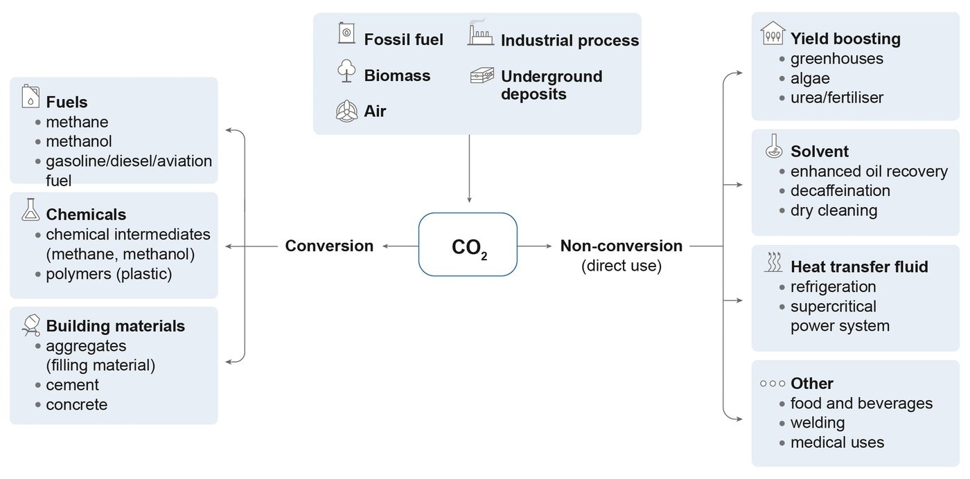
How can CO2 be used?
CO2 can be used as an input to a range of products and services. The potential applications for CO2 use include direct use, where the CO2 is not chemically altered (non-conversion), and the transformation of CO2 to a useful product through chemical and biological processes (conversion).
Simple classification of pathways for CO2 use
Open
Today arund 230 Mt of CO2 are used globally each year, primarily to produce fertilisers (around 125 Mt/year) and for enhanced oil recovery (around 70-80 Mt/year). Other commercial uses of CO2 include food and beverage production, cooling, water treatment and greenhouses. New CO2 use pathways include: fuels (using carbon in CO2 to convert hydrogen into a synthetic hydrocarbon fuel); chemicals (using carbon in CO2 as an alternative to fossil fuels in the production of some chemicals); and building materials (using CO2 in the production of building materials to replace water in concrete or as a raw material in its constituents.) Further detail can be found in the IEA report “Putting CO2 to Use”.
How is CO2 stored – and is it safe?
Storing CO2 involves the injection of captured CO2 into a deep underground geological reservoir of porous rock overlaid by an impermeable layer of rocks, which seals the reservoir and prevents the upward migration or “leakage” of CO2 to the atmosphere. There are several types of reservoir suitable for CO2 storage, with deep saline formations and depleted oil and gas reservoirs having the largest capacity. Deep saline formations are layers of porous and permeable rocks saturated with salty water (brine), which are widespread in both onshore and offshore sedimentary basins. Depleted oil and gas reservoirs are porous rock formations that have trapped crude oil or gas for millions of years before being extracted and which can similarly trap injected CO2.
When CO2 is injected into a reservoir, it flows through it, filling the pore space. The gas is usually compressed first to increase its density and the reservoir typically must be at depths greater than 800 metres to retain the CO2 in a dense liquid-like state. The CO2 is permanently trapped in the reservoir through several mechanisms: structural trapping by the seal, solubility trapping where the CO2 dissolves in the brine water, residual trapping where the CO2 remains trapped in pore spaces between rocks, and mineral trapping where the CO2 reacts with the reservoir rocks to form carbonate minerals (mineralisation). The nature and the type of the trapping mechanisms for reliable and effective CO2 storage, which vary within and across the life of a site depending on geological conditions, are well-understood thanks to decades of experience in injecting CO2 for EOR and dedicated storage.
CO2 storage in basalts (igneous rocks) that have high concentrations of reactive chemicals is also possible, but is in an early stage of development. The injected CO2 reacts with the chemical components to form stable minerals, trapping the CO2.
Global CO2 storage resources are considered to be well in excess of likely future requirements. In many regions, however, significant further assessment work is required to convert theoretical storage capacity into “bankable” storage to support CCUS investment.
How does CCUS support carbon removal?
CCUS technologies can provide a means of removing CO2 from the atmosphere, i.e. “negative emissions”, to offset emissions from sectors where reaching zero emissions may not be economically or technically feasible. There are two principal approaches:
Bioenergy with carbon capture and storage, or BECCS, involves capturing and permanently storing CO2 from processes where biomass (which extracts CO2 from the atmosphere as it grows) is burned to generate energy. A power station fuelled with biomass and equipped with CCUS is a type of BECCS technology, as are facilities that process biomass into biofuels, if the resulting CO2 is captured and stored.
Direct air capture (DAC) involves the capture of CO2 directly from ambient air (as opposed to a point source). The CO2 can be used, for example as a climate-neutral CO2 feedstock in synthetic fuels, or it can be permanently stored for carbon removal.
These technology-based approaches for carbon removal can complement and supplement nature-based solutions, such as afforestation and reforestation.
The role of CCUS in net-zero pathways
In the IEA Sustainable Development Scenario, in which global CO2 emissions from the energy sector fall to zero on a net basis by 2070, CCUS accounts for nearly 15% of the cumulative reduction in emissions compared with the Stated Policies Scenario. The contribution of CCUS grows over time and extends to almost all parts of the global energy system.
World captured CO2 by source in the Sustainable Development Scenario, 2020-2070
OpenCCUS technologies play four strategic roles in the transition to net zero
1) Tackling emissions from existing infrastructure
CCUS can be retrofitted to existing power and industrial plants that could otherwise emit 600 billion tonnes of CO2 over the next five decades – almost 17 years’ worth of current annual emissions.
In the Sustainable Development Scenario an initial focus of CCUS is on retrofitting fossil fuel-based power and industrial plants. By 2030, more than half of the CO2 captured is from retrofitted existing assets.
World CO2 emission reductions from CCUS retrofits in the power generation and heavy industry in the Sustainable Development Scenario, 2019-2070
Open2) A cost-effective pathway for low-carbon hydrogen production
CCUS can support a rapid scaling up of low-carbon hydrogen production to meet current and future demand from new applications in transport, industry and buildings. CCUS is one of the two main ways to produce low-carbon hydrogen.
Global hydrogen use in the Sustainable Development Scenario increases sevenfold to 520 megatonnes (Mt) by 2070. The majority of the growth in low-carbon hydrogen production is from water electrolysis using clean electricity, supported by 3 300 gigawatts (GW) of electrolysers (from less than 0.2 GW today). The remaining 40% of low-carbon hydrogen comes from fossil-based production that is equipped with CCUS, particularly in regions with access to low-cost fossil fuels and CO2 storage.
Global hydrogen production in the Sustainable Development Scenario, 2019-2070
Open3) A solution for the most challenging emissions
Heavy industries account for almost 20% of global CO2 emissions today. CCUS is virtually the only technology solution for deep emissions reductions from cement production. It is also the most cost-effective approach in many regions to curb emissions in iron and steel and chemicals manufacturing. Captured CO2 is a critical part of the supply chain for synthetic fuels from CO2 and hydrogen – one of a limited number of low-carbon options for long-distance transport, particularly aviation.
In the IEA’s Sustainable Development Scenario, CCUS accounts for between one quarter and two-thirds of the cumulative emissions reductions in heavy industry (cement, steel and chemicals production). By 2070, nearly half of global energy demand for aviation is met by synthetic fuels, requiring the capture of around 830 Mt of CO2 for use as feedstock.
World CO2 emissions reductions by abatement measure in the cement sector in the Sustainable Development Scenario relative to the Stated Policies Scenario, 2019-2070
Open4) Removing carbon from the atmosphere
For emissions that cannot be avoided or reduced directly, CCUS underpins an important technological approach for removing carbon and delivering a net-zero energy system.
When net-zero emissions is reached in the Sustainable Development Scenario, 2.9 gigatonnes (Gt) of emissions remain, notably in the transport and industry sectors. These lingering emissions are offset by capturing CO2 from bioenergy and the air and storing it.